How do you install a horn kit on a golf cart

How to Install a Horn Kit on a Golf Cart: Tools, Wiring, Relay & Safety

Add a dependable horn in four clean steps: mount the hardware, route a protected harness, connect via reducer/relay, then test for loud, reliable sound.

Installing a horn kit on a golf cart is a practical upgrade for course driving and neighborhood use. The core process is simple—securely mount the horn, run a protected wiring loom, connect power through a properly fused circuit (and a voltage reducer on multi-battery packs), then verify operation with a safe, methodical test. Below you’ll find the tools and materials you need, a clear step-by-step guide, and pro tips to keep the installation tidy, durable, and serviceable.

Before You Begin: Safety First

  • Power down: Key OFF, charger unplugged, Tow/Run switch to Tow (if equipped).
  • Isolate the pack: Disconnect the main negative cable and secure it away from metal.
  • PPE: Safety glasses and gloves; avoid jewelry that could bridge terminals.
  • Workspace: Level surface, wheel chocks, good lighting, and ventilation.

What tools and materials are needed to install a horn kit on a golf cart?

  • Horn kit (12 V horn, push-button switch, basic harness or pigtails)
  • Voltage reducer (36/48→12 V) sized for at least 2× the horn’s current draw
  • Automotive relay (SPST/40 A) and inline fuse holder with appropriate blade fuse
  • Primary wire (14–16 AWG for most horns; check manufacturer spec)
  • Terminals & protection: Ring/spade terminals, heat-shrink, split loom, cable ties, grommets, dielectric grease
  • Mounting hardware: Stainless bolts, washers, nylock nuts, threadlocker
  • Tools: Drill and bits, crimper/stripper, socket set, screwdrivers, multimeter, deburring tool

1. Mount the horn and switch

Horn location: Choose a rigid frame or brush-guard area, forward-facing but tucked away from standing water. Keep the horn opening down or slightly forward to shed moisture and reduce debris ingestion. Use rubber isolators if supplied to limit vibration. Mark and drill pilot holes, deburr, and secure with stainless hardware and threadlocker.

Switch location: Place the push-button on the dash within thumb reach of the steering wheel. Confirm clearances behind the panel, then drill the manufacturer-specified hole. Install the switch and note the terminal markings (NO/COM or + / −).

2. Run the wiring

  • Harness path: Follow factory looms along roof struts or frame rails. Avoid steering shafts, suspension travel, brake linkages, and sharp edges.
  • Protection: Use split loom and zip ties every 20–30 cm. Add rubber grommets wherever wires pass through metal.
  • Labeling: Tag wires at both ends (e.g., “Horn +”, “Relay 86”, “Switch feed”) to simplify service later.

3. Connect the electrical components

Why a reducer? Many carts use 36 V or 48 V packs. Tapping two or three batteries for 12 V causes pack imbalance. A 12 V voltage reducer draws evenly from the entire pack, protecting both batteries and accessories.

Recommended 12 V relay circuit (clean and reliable)
  1. Reducer 12 V + → Fuse → Relay pin 30
  2. Relay pin 87 → Horn + (horn negative to chassis/12 V −)
  3. Reducer 12 V − → Chassis/negative bus
  4. Switch feed (ignition/accessory 12 V) → Relay pin 86
  5. Relay pin 85 → Ground

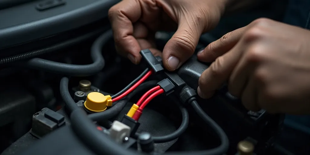
Place the fuse close to the 12 V source (reducer output). Size the fuse to the horn’s current draw (e.g., 10–15 A for typical units). Use 14 AWG for runs under 10 ft; step up a gauge for longer paths or higher-draw air horns. Crimp with the correct die, heat-shrink all joints, and apply a dab of dielectric grease to keep moisture out.

4. Test the installation

  1. Re-energize safely: Reconnect the main negative cable, switch to Run, and turn the key ON (if required).
  2. Meter checks: Verify 12–13 V at relay pin 30 and horn positive. Confirm a good ground at the horn and relay.
  3. Function test: Press the switch. You should hear a strong, clean tone with no dimming or fuse blow.
  4. Rattle check: Drive a short loop over small bumps; re-torque horn hardware and tidy any wire slack.

Troubleshooting at a Glance

  • No sound: Check fuse first; verify reducer output; confirm switch power to relay pin 86; ensure relay clicks.
  • Weak tone: Undersized wire or poor ground. Shorten the run or upgrade to heavier gauge; clean ground point to bare metal.
  • Intermittent: Loose spade terminals or vibration at the horn bracket—re-crimp and add threadlocker.
  • Blown fuse: Short to chassis or horn draw exceeds fuse rating—inspect for pinched wires and verify horn amperage.

Pro Tips for a Tidy, Long-Lasting Install

  • Use an ignition-controlled feed for the switch so the horn can’t be pressed with the cart powered down.
  • Mount the reducer in a cool, ventilated spot away from battery fumes; follow its polarity and pack-voltage directions exactly.
  • Service access: Leave gentle service loops near the horn and relay; label the fuse value on the holder.
  • Noise direction: Aim the horn opening away from wheel splash and toward open air for best volume.

Why the Relay and Fuse Matter

Relays keep higher current away from small dash switches, reducing heat and voltage drop, while a properly sized fuse protects your wiring in the event of a short. Together with a reducer, they form a robust system that won’t stress your battery pack or melt a harness under load.

Summary

Mount the horn on a rigid front location, place the push-button within easy reach, route a protected harness, and power the circuit through a fused 12 V reducer feeding a relay. Test with a multimeter before the first honk, then confirm on-road with a quick rattle check. With careful wire management and proper protection, your horn kit will deliver loud, reliable sound—and a clean, professional look that’s easy to service later.

Leave a Reply

tara golf cars, tara electric golf cars, tara golf fleet, best golf car, fleet cars, 2025, club car, ezgo, yamaha, alternatives, golf courses, golf club,
[newsletter_form]