Upgrading mirrors with integrated turn signals boosts visibility and keeps groups coordinated. Follow this simple wiring plan to add signal mirrors to your cart safely.
To wire signal mirrors on your golf cart, first mount the mirrors to the roof struts, then route the mirror harness (red = signal, black = ground) down the strut into the dash. Inside the dash, locate the turn-signal outputs from the headlight/indicator bundle—commonly blue/black for left and green/black for right—and connect each mirror’s red lead to the correct turn wire and the black lead to chassis/battery negative. Test both sides before final tie-down. (Note: wire colors vary by model—always verify with a multimeter.)
Confirm that your signal circuit is 12V. If your lighting/indicator kit already runs at 12V, tap those lines. If you must pull from a higher-voltage pack (36/48/72V), use a 12V reducer and protect new circuits with an inline fuse. Disconnect the pack negative before any wiring to prevent shorts.
Position each mirror on the A-pillar/roof strut so the glass is centered at eye level and clears the windshield frame. Mark the holes, install the clamps or brackets, and snug them just enough to hold position while you aim. Leave final tightening for the end.
Feed the mirror’s pigtail into the strut channel (or along the inside edge) and down behind the dash. Use split-loom for chafe protection anywhere the harness touches metal. Add a rubber grommet where a wire passes through sheet metal. Keep wiring away from hinge points and steering linkages; secure every 8–10 inches with zip ties.
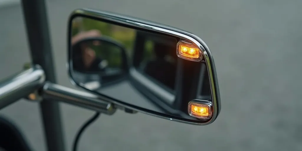
Locate the existing turn-signal leads from your indicator switch or headlight assembly. Many carts use blue/black = left and green/black = right; verify with a multimeter (probe for 12V flashing when each side is activated). Make these connections:
Use T-taps for reversible installs, or solder and heat-shrink for maximum durability. If you are adding a fresh 12V feed (not using the existing turn circuit), run it from your reducer through an inline 3–5A fuse, then to the signal switch output. A dab of dielectric grease on terminals helps resist corrosion.
Reconnect the pack negative and turn on the key. Test left, right, and hazards (if equipped). Confirm each mirror flashes in sync with the front/rear indicators and that no side glows faintly when off. If anything is reversed, swap the left/right connections at the taps. Once confirmed, finalize by tightening brackets and trimming excess zip-tie tails.
Mirror Red (L) ──────▶ Left turn signal output (verify: often blue/black)
Mirror Red (R) ──────▶ Right turn signal output (verify: often green/black)
Mirror Black (both) ─▶ Clean ground point (chassis or battery negative)
Signal mirrors are a high-value upgrade for awareness and group coordination, but the wiring takes careful routing, sound splices, and clean grounds. If you prefer a turnkey solution—or want a factory-style setup with integrated lighting—consider a model like the Tara Roadster 2. It delivers a cohesive lighting package out of the box, letting you focus on the fun rather than the wiring.
